Software architecture is the backbone of any successful digital product. At the heart of this backbone lies the deployment diagram, a critical artifact that maps out the physical hardware, software components, and network infrastructure. However, even the most meticulously crafted diagrams can suffer from scope creep, a phenomenon where project requirements expand uncontrollably, often derailing timelines and budgets. This guide provides a deep dive into preventing scope creep specifically within the context of deployment planning, ensuring your infrastructure designs remain stable, scalable, and aligned with business goals.
Understanding Deployment Diagrams and Their Role 📊
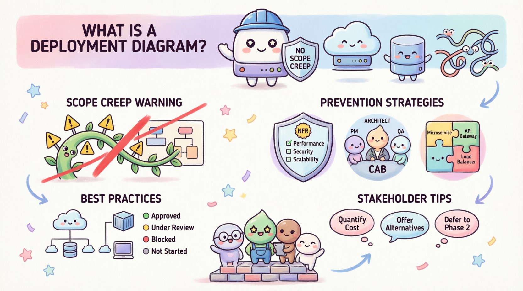
A deployment diagram is a visual representation of the hardware topology and software components. It shows how software artifacts are deployed onto execution nodes. Unlike a class diagram which focuses on structure, or a sequence diagram which focuses on interaction, the deployment diagram focuses on where things run. It answers questions like: Where does the database live? How are the API gateways distributed? What are the security boundaries?
When these diagrams become bloated with unnecessary details or unverified assumptions, they lose their value. Scope creep in this context often manifests as adding nodes without justification, assuming connectivity that doesn’t exist, or planning for hardware that isn’t budgeted.
Key Elements of a Deployment Diagram
- Nodes: Physical or virtual computing resources (servers, containers, devices).
- Artifacts: Executable files, libraries, or data stores deployed to nodes.
- Communication Paths: The network connections linking nodes (HTTP, TCP, WebSocket).
- Interfaces: The points of interaction between components.
- Constraints: Latency limits, security policies, or hardware specifications.
Defining Scope Creep in Infrastructure Planning 📉
Scope creep is not just about adding features to code. In deployment architecture, it is about adding complexity to the environment. It occurs when stakeholders request additional infrastructure components that were not part of the initial agreement.
Common Manifestations of Infrastructure Scope Creep
- Unplanned Environment Splits: Moving from a single staging environment to multiple isolated zones without a technical justification.
- Hardware Over-Provisioning: Specifying high-end servers for low-traffic services due to “just in case” thinking.
- Redundancy Without Strategy: Adding secondary regions or availability zones without a disaster recovery plan.
- Third-Party Integrations: Adding external services (payment gateways, analytics) that introduce new network dependencies and security risks.
When these elements appear in a deployment diagram late in the process, they force rework. The diagram must be treated as a contract between the development team and the infrastructure team. If the contract changes without approval, the project suffers.
Pre-Deployment Strategies to Prevent Creep 🛡️
The best time to stop scope creep is before the diagram is drawn. A disciplined planning phase sets boundaries that protect the architecture from unnecessary expansion.
1. Define Clear Non-Functional Requirements (NFRs)
Before drawing a single box, define the constraints. If you know the system must handle 10,000 concurrent users with less than 200ms latency, the diagram must reflect the infrastructure needed to meet that. If a stakeholder later asks for 100,000 users, that is a new requirement, not a scope creep adjustment.
- Performance: Define throughput and response time goals.
- Reliability: Define uptime percentages (e.g., 99.9%).
- Security: Define encryption standards and compliance needs.
- Cost: Set a ceiling for infrastructure expenditure.
2. Establish a Change Control Board (CCB)
Not every diagram change is valid. Implement a process where any addition to the deployment topology requires review. This does not mean stifling innovation, but rather ensuring that every new node or connection has a documented business case.
3. Standardize Infrastructure Patterns
Adopt standard patterns for deployment. For example, always place load balancers in front of web servers. Always isolate databases from application servers. Standardization reduces the cognitive load on the diagram and makes it easier to spot anomalies that might indicate scope creep.
Managing Changes During Development 🔄
Even with the best planning, requirements change. The goal is to manage these changes without allowing them to spiral out of control. The deployment diagram must evolve in lockstep with the codebase.
Version Control for Diagrams
Just as you version your code, you must version your diagrams. Use a version control system to track changes to the architecture files. This allows you to revert if a change proves too costly or unnecessary.
- Commit Messages: Document the reason for every architectural change.
- Branching: Create branches for experimental architectures before merging them to the main line.
- Review: Require peer review for any diagram modification.
Impact Analysis
When a new component is requested, perform an impact analysis. How does this new node affect the existing network? Does it introduce new latency? Does it require new security protocols? If the answer is “yes,” ensure the cost is understood.
Documentation of Assumptions
Often, scope creep stems from assumptions made by the architect. If you assume a certain cloud provider feature is available, and it isn’t, you have to redesign. Write down every assumption. If an assumption changes, trigger a formal review of the diagram.
Common Pitfalls in Deployment Planning ⚠️
Understanding what goes wrong is as important as knowing what goes right. The following table outlines common pitfalls that lead to scope creep and how to mitigate them.
| Pitfall | Impact | Mitigation Strategy |
|---|---|---|
| Over-Engineering | Building for a future scale that doesn’t exist yet. | Use horizontal scaling patterns that can be enabled later. |
| Vendor Lock-in | Adding proprietary services that restrict future flexibility. | Prefer open standards and abstraction layers. |
| Network Oversight | Ignoring bandwidth limits between nodes. | Map network topology explicitly and calculate bandwidth. |
| Security Gaps | Adding nodes that bypass security gateways. | Enforce a security-first design pattern for all connections. |
| Environment Drift | Production looks different from Staging. | Use Infrastructure as Code (IaC) to enforce consistency. |
Best Practices for Maintaining Diagram Integrity ✅
To keep deployment diagrams effective and free from scope creep, adhere to these operational best practices.
1. Keep It High-Level Initially
Do not start with every microservice and database table. Start with the major nodes: Load Balancer, Application Server, Database, Cache. As the project matures, refine the diagram. Starting too granular invites unnecessary detail that leads to scope creep.
2. Use Color Coding for Status
Visual cues help teams understand the maturity of a component. Use colors to denote:
- Green: Implemented and stable.
- Yellow: Planned or in progress.
- Red: Problematic or deprecated.
- Gray: Future consideration (not in current scope).
This makes it immediately obvious when someone adds a “Red” item to the diagram, signaling a deviation from the plan.
3. Align Diagrams with CI/CD Pipelines
The deployment diagram should reflect the actual deployment pipeline. If the pipeline deploys to three environments, the diagram should show three nodes or a clear grouping. If the pipeline changes, the diagram must change. This alignment prevents the “diagram on the shelf” syndrome where the visual plan no longer matches reality.
4. Regular Architecture Reviews
Schedule quarterly reviews of the deployment architecture. Ask the team: “Does this diagram still match what we are building?” If not, update it. If a component is no longer needed, remove it. This cleaning process prevents the accumulation of dead weight.
Handling Stakeholder Requests 🗣️
Stakeholders often drive scope creep by asking for “just one more thing.” Here is how to handle those requests professionally.
- Quantify the Cost: Explain how adding a new node increases latency, cost, or maintenance burden.
- Offer Alternatives: If they want a feature, can it be achieved without changing the infrastructure? Perhaps via configuration rather than new hardware.
- Defer to Phase 2: Acknowledge the request but schedule it for the next iteration. This keeps the current diagram stable.
- Visual Evidence: Show the diagram. Point out where the new item fits. If it breaks a pattern, explain why.
Technical Debt and Deployment Diagrams 🏗️
Scope creep often creates technical debt in the infrastructure layer. When you add a node without proper planning, you create a dependency that is hard to remove later. This debt compounds over time.
Indicators of Infrastructure Technical Debt
- Multiple manual steps required to deploy to a new node.
- Hardcoded IPs or hostnames in the diagram that don’t match the environment.
- Unclear ownership of specific nodes.
- Missing documentation for data flows between nodes.
Preventing scope creep is the best way to avoid this debt. Treat the deployment diagram as a living document that requires maintenance, not a one-time deliverable.
Conclusion: Stability Through Discipline 🧭
Effective deployment diagrams are more than just drawings; they are blueprints for stability. By defining clear boundaries, managing changes rigorously, and maintaining a disciplined approach to documentation, you can prevent scope creep from undermining your infrastructure plans. The goal is not to stop change, but to manage it in a way that aligns with the project’s core objectives. When your diagrams remain clean and accurate, your deployment processes become predictable, your costs remain controlled, and your team can focus on building value rather than fixing architectural mistakes.
Remember, a deployment diagram is a communication tool. Its primary job is to ensure everyone agrees on the physical reality of the system. If the diagram changes without consensus, that communication has failed. Protect the integrity of your architecture, and you protect the success of your project.