Designing complex systems requires precision. When you create an Interaction Overview Diagram (IOD), you are mapping the dynamic behavior of a system. However, a common challenge arises during development: the logic depicted in the diagram does not align with how the actual software behaves. This discrepancy can lead to costly debugging cycles and architectural instability. This guide provides a structured approach to identifying and resolving these issues without relying on specific tools or hype.
📊 The goal is simple: ensure your visual representation matches the runtime reality. We will explore the anatomy of IODs, diagnose common logic errors, and establish validation protocols. By following this process, you can maintain system integrity and reduce the gap between design and implementation.
🧩 Understanding the Interaction Overview Diagram
An Interaction Overview Diagram combines elements of Activity Diagrams and Sequence Diagrams. It provides a high-level view of control flow, decision points, and the sequencing of interactions. Unlike a pure Sequence Diagram, which focuses on one scenario, an IOD can orchestrate multiple scenarios.
Key Components
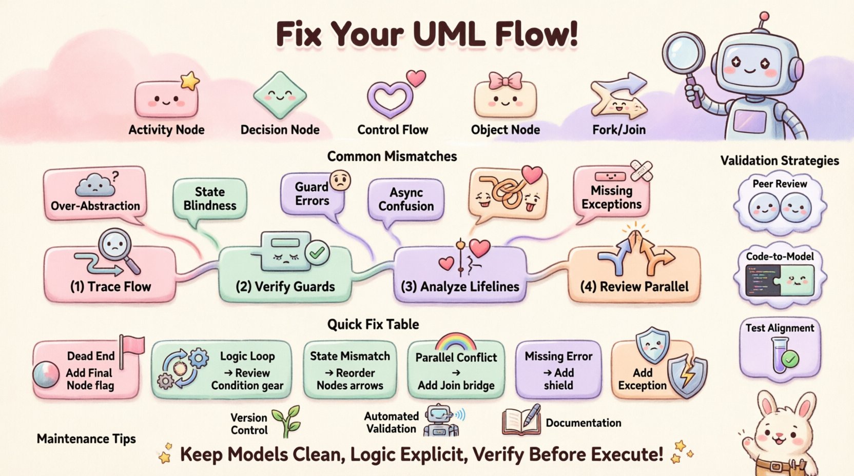
- Activity Nodes: Represent actions or operations being performed.
- Decision Nodes: Diamond shapes indicating branching paths based on conditions.
- Control Flow: Arrows connecting nodes to show the order of execution.
- Object Nodes: Represent data or state changes within the flow.
- Fork/Join Nodes: Indicate parallel execution paths.
When these elements are configured correctly, the diagram serves as a blueprint for developers. When they are not, the blueprint becomes misleading.
🚨 Why Flow Logic Mismatches Occur
It is common to encounter situations where the code executes differently than the model suggests. Understanding the root causes is the first step toward resolution. These mismatches usually stem from abstraction gaps, timing issues, or state management errors.
Common Causes of Discrepancy
- Over-Abstraction: The diagram simplifies complex logic too much, hiding critical edge cases.
- State Blindness: The diagram assumes a state that the system does not possess at a specific moment.
- Guard Condition Errors: Logic gates (if/else) are defined incorrectly in the model.
- Asynchronous Confusion: Parallel processes are modeled as sequential or vice versa.
- Missing Exception Paths: Error handling flows are omitted from the primary diagram.
When developers implement the system, they often fill in the gaps with their own assumptions. If the diagram is vague, the implementation will diverge. This divergence creates the “flow logic mismatch”.
🔍 Step-by-Step Troubleshooting Protocol
Resolving these issues requires a methodical audit. Do not rush to change the code or the diagram immediately. Follow this diagnostic sequence to isolate the problem.
1. Trace the Control Flow Manually
Start with a human review. Walk through the diagram from start to finish. For every decision node, verify that the outgoing paths cover all possible outcomes. Ask yourself:
- Does every path lead to a termination point?
- Are there any dead ends where the flow stops without an error message?
- Do the conditions on the decision nodes overlap or leave gaps?
If you find a path that is not covered by the code, that is a primary source of the mismatch.
2. Verify Guard Conditions
Guard conditions are the logic rules attached to transitions. They determine which path the flow takes. A common error is writing a condition in the diagram that does not match the code’s conditional statement.
- Check Syntax: Ensure the logical operators (AND, OR, NOT) are identical in the model and the code.
- Check Variables: Verify that the variables referenced in the guard condition exist in the scope of the action.
- Check Data Types: Ensure the comparison types match (e.g., integer vs string).
3. Analyze Object Lifelines
Interaction Overview Diagrams often reference specific objects or components. If an object is created or destroyed at a different point in the code than shown in the diagram, the interaction flow breaks.
- Map the lifecycle of each object in the diagram.
- Compare this with the instantiation and destruction points in the source code.
- Ensure that messages sent to an object are sent only when the object is active.
4. Review Parallel Execution
Fork and Join nodes introduce concurrency. Misinterpreting how these work is a frequent source of bugs.
- Does the code actually run these paths simultaneously?
- Is there a synchronization point that is missing in the implementation?
- Are race conditions possible due to shared state access?
✅ Validation Strategies
Once you have identified potential issues, you must validate your fixes. Relying solely on the diagram is insufficient. Use the following strategies to confirm alignment.
Peer Walkthroughs
Invite a colleague who did not create the diagram to review it. Ask them to simulate the flow using the code as a reference. A fresh perspective often catches assumptions you have made.
Code-to-Model Comparison
Perform a line-by-line comparison of critical sections. Highlight the code blocks that correspond to specific nodes in the diagram. If a code block performs multiple actions not shown in the diagram, update the model.
Test Case Alignment
Ensure your test cases cover every branch in the IOD. If a test case exists that is not represented in the diagram, the diagram is incomplete. Conversely, if a diagram branch has no corresponding test, it may be dead code.
🛠️ Common Errors and Solutions Table
Use this reference table to quickly identify typical pitfalls and their corresponding corrective actions.
| Issue Category | Symptom | Potential Cause | Corrective Action |
|---|---|---|---|
| Dead Ends | Flow stops unexpectedly during execution. | Missing final node or transition. | Add a final node to every branch path. |
| Logic Loops | System hangs or enters infinite loops. | Incorrect loop conditions in decision nodes. | Review guard conditions for termination criteria. |
| State Mismatch | Actions fail because object is null. | Object created after message sent. | Adjust order of nodes in the flow. |
| Parallel Conflicts | Unpredictable behavior in concurrent tasks. | Missing Join node or synchronization. | Ensure Join nodes wait for all Fork paths. |
| Missing Error Handling | System crashes on invalid input. | Exception paths not modeled. | Add exception flows to the diagram. |
🔄 Maintaining Diagram Accuracy
Once the flow logic matches, the work is not done. Systems evolve. A diagram that is accurate today may be obsolete tomorrow. Maintenance is a continuous process.
Version Control Integration
Treat diagrams as code. Store them in the same repository and version them alongside the source code. When a code commit changes logic, the diagram should be reviewed for updates.
Automated Validation
If possible, use scripts to parse the model and the code for structural consistency. While manual review is best, automated checks can catch missing nodes or orphaned transitions.
Documentation of Changes
When you update a diagram, document why. Was it a bug fix? A feature addition? This history helps future maintainers understand the evolution of the logic.
📉 Handling Complex Scenarios
Some systems are too complex for a single diagram. In these cases, breaking down the logic is necessary.
Modularization
Split the Interaction Overview into smaller sub-diagrams. Focus on one module or feature at a time. This reduces cognitive load and makes mismatches easier to spot.
Reference Nodes
Use reference nodes to point to other diagrams. If a complex sequence is detailed elsewhere, reference that diagram in the high-level overview. This keeps the main diagram clean while preserving detail.
👥 Collaborative Review Process
Modeling is rarely a solo activity. Collaboration ensures that the diagram reflects both the architectural intent and the implementation reality.
- Architect Review: Checks if the high-level flow aligns with system design.
- Developer Review: Checks if the flow is implementable with current constraints.
- QA Review: Checks if all testable scenarios are covered.
Regular meetings dedicated to diagram review can prevent drift. These sessions should focus on specific changes rather than the entire model.
🚀 Moving Forward
Resolving flow logic mismatches is about discipline and rigor. It requires a willingness to admit when the model is wrong and the courage to update it. By following a structured troubleshooting approach, you ensure that your diagrams remain reliable artifacts.
Remember, the diagram is a communication tool. If the code does not match the diagram, the communication has failed. Prioritize alignment between the visual representation and the runtime behavior. This alignment leads to stable systems and efficient development cycles.
Keep your models clean. Keep your logic explicit. And always verify the path before you execute it.