Designing complex systems requires more than just coding individual functions. It demands a clear visualization of how different parts of a system communicate and control the flow of data. For mid-level developers, the UML Interaction Overview Diagram (IOD) serves as a critical bridge between high-level architecture and low-level implementation details. Unlike a standard Sequence Diagram which focuses on a single scenario, an IOD combines the structural benefits of an Activity Diagram with the behavioral precision of Interaction Diagrams. This guide provides a comprehensive walkthrough on constructing these diagrams effectively, ensuring your business logic is robust, traceable, and maintainable.
Understanding the Interaction Overview Diagram 🧩
At its core, an Interaction Overview Diagram acts as a high-level map for a set of interactions. It allows you to see the big picture of a workflow without getting bogged down in the minutiae of message passing that dominates Sequence Diagrams. This diagram type is particularly useful when a process involves branching logic, conditional paths, or the orchestration of multiple sub-processes.
Key characteristics include:
- Control Flow Focus: Unlike Activity Diagrams which might focus on data movement, IODs prioritize the control flow between interactions.
- Modularity: You can encapsulate complex interactions within a single node, referencing them as sub-flows.
- Logic Visualization: It excels at showing decision points, loops, and parallel execution paths.
- Developer Context: It is designed for those who understand object lifecycles and message sequences but need to manage the orchestration.
When you approach a blank canvas, the goal is not to draw every message. The goal is to define the path that triggers specific interactions. This distinction is vital for maintaining clarity as the system scales.
Core Elements of an IOD 🛠️
Before drawing the lines, you must understand the building blocks. Each element in an IOD has a specific semantic meaning. Misusing a node type can lead to ambiguity in the requirements specification.
1. Initial and Final Nodes
- Initial Node: A solid black circle representing the starting point of the control flow. Every diagram should have exactly one entry point.
- Activity Final Node: A circle with a dot inside, signifying the successful completion of the entire workflow.
- Interaction Final Node: Similar to the activity final node but specifically indicates the termination of an interaction reference.
2. Control Nodes
These nodes manage the flow of control through the diagram. They determine where the process goes next based on logic.
- Fork Node: A thick horizontal or vertical bar. It splits a single incoming flow into multiple concurrent outgoing flows. Use this when parallel actions are required.
- Join Node: A thick bar that merges multiple incoming flows into one. All incoming paths must be complete before the flow continues.
- Decision Node: A diamond shape. It routes the flow based on a boolean condition (e.g.,
if/elselogic). Ensure each outgoing edge has a guard condition. - Merge Node: A diamond without an arrow inside. It combines multiple alternative flows into a single path without waiting for all of them to complete.
3. Interaction Nodes
This is the unique feature of the Interaction Overview Diagram.
- Call Behavior Action: Represents the invocation of a specific behavior or function.
- Interaction Overview Node: A rectangle with a folded corner icon. It represents a reference to another Interaction Overview Diagram or a complex sub-process.
- Interaction Use: A rectangle with a specific icon (often a sequence diagram symbol). This is the most common element, linking to a Sequence Diagram or Communication Diagram.
To visualize the differences, refer to the table below.
| Element Type | Shape | Primary Function | Typical Use Case |
|---|---|---|---|
| Decision Node | Diamond | Conditional Routing | Handling user input validation |
| Fork Node | Thick Bar | Parallel Execution | Triggering email and logging simultaneously |
| Interaction Use | Rectangle | Reference | Linking to a detailed API sequence diagram |
| Initial Node | Black Circle | Start Point | Entry point for the user session |
Preparing Your Blueprint 📋
Jumping straight into the drawing tool without a plan often leads to tangled logic. Before placing the first node, establish the boundaries of the interaction.
- Define the Scope: What is the start event? What constitutes a successful end? For example, if modeling a
PlaceOrderfunction, the start is the user clicking “Submit”, and the end is the “Order Confirmed” state. - Identify Dependencies: List all external systems or internal services involved. If the process relies on a payment gateway, a third-party inventory check, or a notification service, these will likely become Interaction Use nodes.
- Map the Critical Path: Sketch the happy path on paper first. This is the linear flow where everything goes right. Once this is stable, add the exception handling.
- Group Related Interactions: If you have a complex sequence of messages, consider creating a separate Sequence Diagram for it. Then, reference that diagram in the IOD using an Interaction Use node.
Building the Flow: A Practical Walkthrough 🛤️
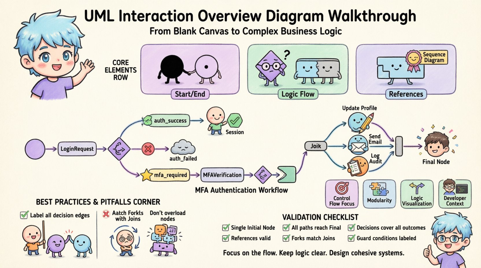
Now, let us move from theory to practice. We will construct a flow for a mid-level developer scenario: User Authentication with Multi-Factor Authentication (MFA) and Session Management. This example covers basic flow, branching, and external interaction.
Step 1: Initiation
Start with the Initial Node. Draw a control flow arrow leading to the first interaction. In this case, it is the LoginRequest interaction. Represent this as an Interaction Use node. This node encapsulates the username and password exchange.
Step 2: Decision Logic
From the LoginRequest node, the flow must determine the outcome. Connect a Decision Node to the outgoing arrow. This node splits the path based on the authentication result.
- Path A (Success): Label the edge
auth_success = true. This leads directly to the session generation logic. - Path B (Failure): Label the edge
auth_failed. This leads to a retry limit check or an error log. - Path C (MFA Required): Label the edge
mfa_required. This is crucial for modern security flows.
Step 3: Handling MFA
If the flow takes the MFA path, draw a new Interaction Use node labeled MFAVerification. This represents the code entry via SMS or Authenticator app. After this interaction, another Decision Node is required.
- Check if the code is valid.
- If invalid, loop back to the
MFAVerificationnode or proceed to an error state after multiple attempts. - If valid, merge this flow back into the main success path.
Step 4: Parallel Processing (Fork)
Once the user is authenticated, you often need to perform background tasks. These do not block the user’s immediate experience. Use a Fork Node after the authentication success.
- Branch 1: Update User Profile Timestamp.
- Branch 2: Send Welcome Email.
- Branch 3: Log Audit Event.
After these branches complete, use a Join Node to synchronize them. The flow only continues once all three branches are finished. This ensures data consistency before the session is officially opened.
Step 5: Termination
Finally, connect the Join Node to the Activity Final Node. This signifies that the login process is complete and the user has access to the system.
Handling Complex Logic Patterns 🔄
Real-world business logic rarely follows a straight line. Mid-level developers often encounter scenarios involving loops, retries, and state management. Here is how to model these patterns within an IOD.
1. Retry Mechanisms
Network calls are unreliable. You will need to model a retry loop. Use a Decision Node after the external call interaction.
- Check the
retry_count. - If
retry_count < max_retries, draw an arrow looping back to the Interaction Use node. Add a guard condition likeretry_needed. - If
retry_count >= max_retries, route to an error handler node.
Tip: Ensure the loop has an exit condition to prevent infinite cycles in the diagram.
2. Exception Handling
Exceptions should not be an afterthought. Create a dedicated branch for error states. If a CallBehaviorAction fails, it can trigger an exception path. Use a Final Node specifically for errors to indicate that the process terminated due to a fault, not a successful completion.
3. Nested Interactions
Complexity can grow quickly. If a specific branch requires more than 10 nodes, it becomes unreadable. Break it down. Create a separate Interaction Overview Diagram for that sub-process. Reference it using an Interaction Overview Node.
- Parent Diagram: High-level flow of the checkout process.
- Child Diagram: Detailed logic for tax calculation and shipping validation.
This hierarchy keeps the main diagram clean while preserving detail where needed.
Integrating with Sequence Diagrams 🔗
An Interaction Overview Diagram does not exist in isolation. It is part of a larger UML ecosystem. The most common integration is with Sequence Diagrams.
When to Use Which?
- Use a Sequence Diagram when the order of messages between objects is the most important detail. Use this for debugging specific method calls.
- Use an Interaction Overview Diagram when the sequence of high-level steps is the focus. Use this for designing workflows, state machines, and business processes.
Best Practices for Integration
When referencing a Sequence Diagram within an IOD:
- Ensure the Interaction Use node in the IOD matches the entry point of the Sequence Diagram.
- Keep the naming conventions consistent. If the IOD node is named
ProcessPayment, the Sequence Diagram should share that title or a clear alias. - Document parameters. If the IOD passes a
TransactionIDto the Sequence Diagram, note this in the diagram legend or a requirements document.
Common Pitfalls and How to Avoid Them ⚠️
Even experienced architects make mistakes when modeling. Being aware of common traps saves time during code reviews and implementation.
- Overloading Nodes: Do not put too much logic inside a single Interaction Use node. If the node description grows to a paragraph, split the logic into sub-diagrams.
- Ignoring Guard Conditions: Every outgoing edge from a Decision Node must have a label. If you have two edges, use
trueandfalse. If you have three, use specific values likestatus=active,status=pending. - Deadlocks: Check for Join Nodes that wait for a path that never arrives. Ensure every fork has a corresponding join.
- Infinite Loops: Review loops carefully. Is there a mechanism to break the loop? If the logic relies on an external system that might never respond, the diagram is theoretically correct but practically flawed.
- Mixing Control and Object Flow: IODs primarily model control flow. Do not use object flow arrows (dashed lines) to pass data between Interaction Use nodes unless it is strictly necessary. Keep the focus on the sequence of operations.
Maintenance and Lifecycle Management 🔁
Once the diagram is created, it is a living document. As the software evolves, the diagram must evolve with it. This section outlines how to manage the diagram throughout the development lifecycle.
Version Control
Treat the diagram file like code. Store it in your version control system. Commit changes when:
- A new interaction path is added.
- A business rule changes (e.g., MFA becomes mandatory for all users).
- External dependencies are updated.
Review Process
Include Interaction Overview Diagrams in your code review cycle, especially for backend logic.
- Peer Review: Ask a colleague to trace the logic on the diagram without looking at the code. Can they find the error path?
- Architecture Review: Ensure the diagram aligns with the high-level system architecture. Does the flow match the service boundaries?
Refactoring
If you refactor code, check the diagram. Often, developers update the code but forget to update the documentation. This leads to a drift between the implementation and the design. Schedule periodic reviews of the diagram library to ensure accuracy.
Validation Checklist ✅
Before marking the diagram as complete, run through this validation checklist.
| Check | Criteria |
|---|---|
| Entry Point | Is there exactly one Initial Node? |
| Exit Points | Are all paths leading to a Final Node? |
| Logic Coverage | Do all decision nodes cover all possible outcomes? |
| Referencing | Are all Interaction Use nodes linked to valid Sequence/IOD files? |
| Parallelism | Do all Fork nodes have a matching Join node? |
| Clarity | Are guard conditions labeled on all decision edges? |
By adhering to these standards, you ensure that the diagram serves its purpose: a reliable blueprint for implementation. The Interaction Overview Diagram is a powerful tool for mid-level developers who want to move beyond writing code in isolation and start designing cohesive systems.
Focus on the flow. Keep the logic clear. Use the nodes correctly. With practice, you will find that these diagrams reduce ambiguity, streamline communication with stakeholders, and significantly lower the risk of logic errors during development.