
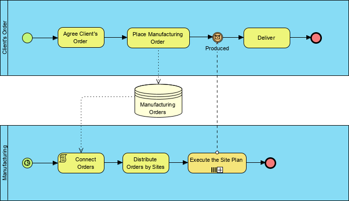
Welcome to this comprehensive tutorial on Business Process Model and Notation (BPMN) 2.0. In this guide, we will dissect a complex process diagram that bridges the gap between a client’s request and the manufacturing execution phase. We will specifically focus on the critical role of Artifacts, particularly the Data Store, and how they facilitate the flow of information between distinct organizational pools.
Understanding the Architecture of the Diagram
The diagram provided illustrates a classic “Swimlane” or “Pool” architecture. This structure is fundamental in BPMN for separating responsibilities and clarifying which entity is performing a specific task. In our scenario, the process is divided into two distinct pools:
- Client’s Order Pool: Represents the commercial and administrative side of the business, handling agreements, orders, and final delivery.
- Manufacturing Pool: Represents the operational side, responsible for the physical execution of the work.
The magic happens in the interaction between these two pools. They do not exist in isolation; they communicate via a shared data repository. This is where the concept of a Data Store becomes vital.
Deep Dive: The Data Store Artifact
In the center of the diagram, between the two pools, sits a cylinder labeled “Manufacturing Orders”. In BPMN terminology, this is a Data Store.
Unlike a Data Object, which represents transient information (like a specific document or form) that exists only during the process execution, a Data Store represents a persistent repository. This means:
- Permanence: The data stored here remains available even after the current process instance is finished. Future processes can retrieve this data later.
- External Dependency: It acts as a bridge. The “Client’s Order” pool does not directly talk to the “Manufacturing” pool’s tasks. Instead, it writes data to the store, and the Manufacturing pool reads from it.
Mapping the Data Flow
Let’s trace how data moves through this system using Associations (dashed lines) that connect the artifacts to the activities:
- Writing Data: When the activity Place Manufacturing Order is completed in the top pool, it sends the order details to the Manufacturing Orders Data Store. This “commits” the request to the system.
- Reading Data: In the bottom pool, the activity Connect Orders is linked to the same Data Store. This indicates that the system is fetching the orders that were previously saved. This ensures the manufacturing team only works on orders that have been officially placed.
Step-by-Step Process Flow Analysis
Phase 1: The Client’s Order (Top Swimlane)
- Start: The process begins when a client places an order.
- Agree Client’s Order: The business negotiates and agrees on the terms with the client. This is a manual or administrative task.
- Place Manufacturing Order: Once agreed, the system generates a formal manufacturing order. This is the trigger point that saves data to the Manufacturing Orders Data Store.
- Produced: The system waits for a signal. The dashed line labeled “Produced” looping back from the manufacturing pool indicates a synchronization. The top pool cannot proceed until the bottom pool signals completion.
- Deliver: Upon receiving the signal that production is complete, the business proceeds to deliver the final product.
- End: The process concludes with a successful delivery.
Phase 2: Manufacturing (Bottom Swimlane)
- Start: The manufacturing process starts independently (or triggered by the data arrival) with the Connect Orders activity.
- Distribute Orders by Sites: The system takes the retrieved orders and distributes them to specific manufacturing sites or teams. This implies a logic of routing tasks based on capacity or location.
- Execute the Site Plan: The actual work is performed. The icon (a factory or machine) inside this box suggests an automated or specialized execution step.
- Signal Return: Once the plan is executed, a signal is sent back to the top pool (the “Produced” path), closing the loop.
Why Use Artifacts for Context Customization?
As noted in BPMN specifications, this flexibility allows modelers to tailor diagrams to specific vertical markets. In a banking context, a Data Store might be “Loan Applications.” In insurance, it could be “Claims Files.” In our manufacturing context, “Manufacturing Orders” is the critical entity.
By using the Data Store artifact, we avoid cluttering the diagram with complex gateways or message flows for every single data transfer. Instead, we establish a clean, centralized “database” view that clearly shows which parts of the process rely on shared state.
Conclusion
This diagram effectively demonstrates a synchronized process where administrative actions (Order Placement) and operational actions (Manufacturing) are decoupled yet synchronized via a shared Data Store. Using the Data Store artifact allows us to visualize the “memory” of the system, ensuring that the manufacturing team always has access to the latest agreed-upon orders.
Tooling: Visual Paradigm
To replicate this architecture in your own projects, you can utilize Visual Paradigm, a robust tool for BPMN modeling.
- Creating the Data Store: Simply drag the “Data Store” shape from the palette onto your canvas. It is distinct from the “Data Object” and is visually represented as a cylinder.
- Connecting Artifacts: Use the “Association” tool (dashed line) to link your Data Store to the relevant tasks. This establishes the read/write relationships clearly.
- Swimlanes: Visual Paradigm makes it easy to create the “Client’s Order” and “Manufacturing” pools using the “Pool” and “Lane” tools, ensuring your diagram remains organized and professional.