


In modern software architecture, the deployment diagram serves as the critical blueprint for how application components interact with the underlying infrastructure. When this blueprint diverges from reality, the result is often a failed deployment. These failures can stem from configuration errors, network misconfigurations, or logical inconsistencies within the diagram itself. Understanding these common pitfalls is essential for maintaining system reliability and ensuring that the visual representation of your architecture accurately reflects the operational environment. This guide explores the root causes of deployment failures related to diagrammatic inaccuracies and provides a structured approach to troubleshooting them.
Why Deployment Diagrams Matter for Stability 📋
A deployment diagram is not merely a static image; it is a dynamic contract between the design phase and the execution phase. It defines nodes, artifacts, and the connections that bind them. When the diagram is outdated or incorrect, automated deployment pipelines receive conflicting instructions. For instance, if a diagram indicates a database node exists but the infrastructure provisioning script does not account for it, the deployment process halts. Conversely, if the diagram omits a necessary firewall rule, the deployment might succeed initially but fail during runtime due to connectivity restrictions.
The accuracy of these diagrams directly impacts:
- Deployment Speed: Incorrect diagrams lead to manual intervention and delays.
- System Reliability: Mismatches cause runtime errors and service outages.
- Security Posture: Unvisualized network paths can expose sensitive data flows.
- Cost Efficiency: Provisioning errors often result in wasted compute resources.
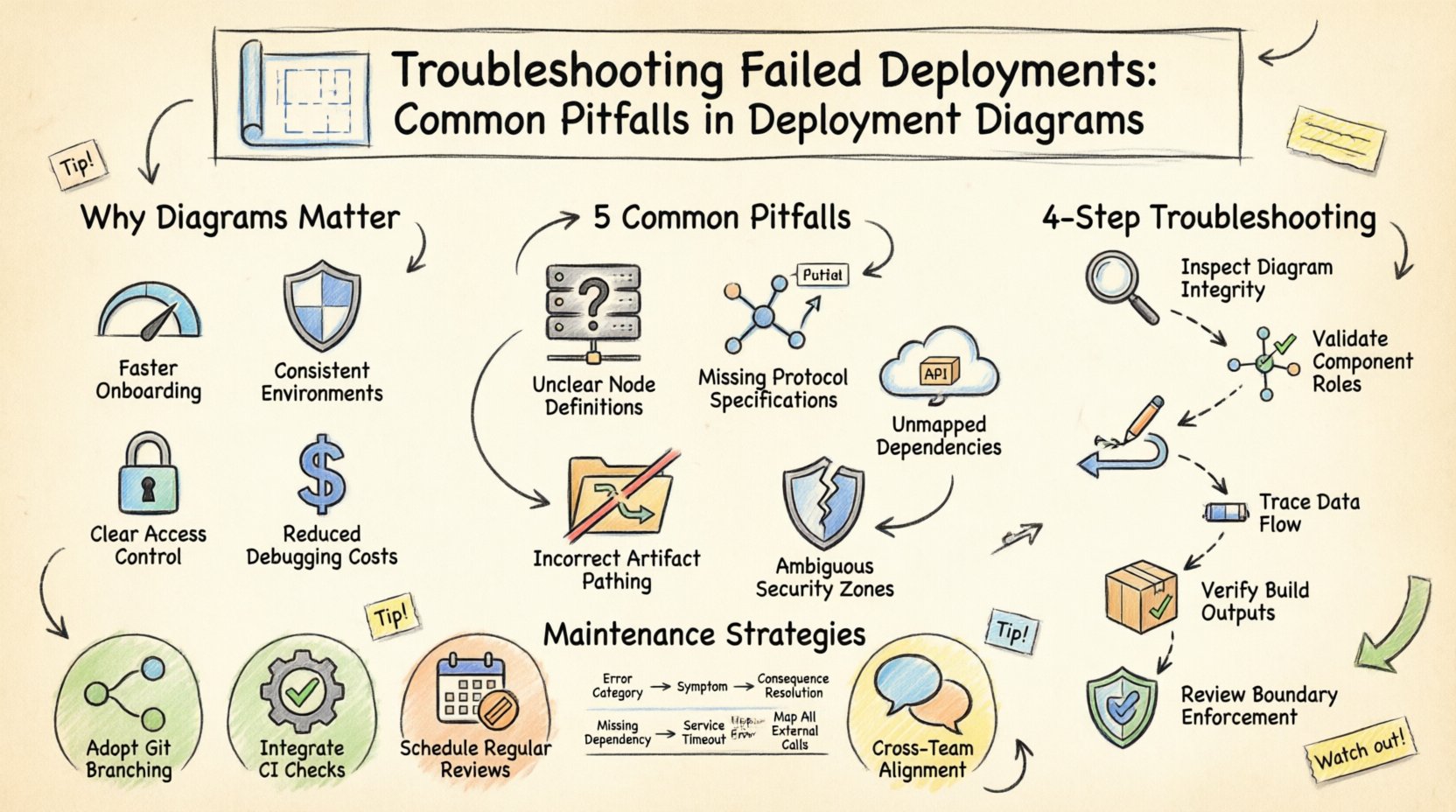
Common Pitfalls in Deployment Diagrams ⚠️
Identifying the source of a deployment failure often requires a forensic review of the architectural documentation. Below are the most frequent errors found within deployment diagrams that lead to operational issues.
1. Missing or Incorrect Node Definitions 🖥️
Nodes represent physical or virtual execution environments. A common error occurs when the hardware specifications or software environment required by a node are not explicitly defined. If a node is labeled as a generic server without specifying the operating system or runtime version, the deployment tool may attempt to install software on an incompatible platform.
- Issue: Node type does not match the actual infrastructure.
- Impact: Deployment scripts fail to execute commands or locate dependencies.
- Visual Indicator: Generic icons without specific configuration labels.
2. Undefined Communication Protocols 🌐
Connections between nodes represent data flow. If the protocol (e.g., HTTP, TCP, HTTPS, gRPC) is not specified on the connecting line, the deployment logic may default to an insecure or unsupported method. This is particularly dangerous in environments with strict security policies.
- Issue: Ambiguous or missing protocol specifications on links.
- Impact: Services cannot establish handshake connections.
- Visual Indicator: Arrows without protocol labels or port numbers.
3. Overlooked External Dependencies 📦
Architectures rarely exist in a vacuum. They rely on external services, APIs, or third-party databases. Deployment diagrams often fail to represent these external boundaries clearly. If an external API endpoint is required but not depicted, the deployment process will not provision the necessary authentication credentials or network routes.
- Issue: External artifacts are treated as internal or omitted entirely.
- Impact: Runtime errors when calling external services.
- Visual Indicator: Missing boundary markers for third-party systems.
4. Incorrect Artifact Pathing 📂
Deployment diagrams often show artifacts (the actual software packages) residing on nodes. If the path to these artifacts is not accurate or if the artifact version is not specified, the deployment system cannot locate the binary to install. This leads to “file not found” errors during the provisioning phase.
- Issue: Artifact paths are relative or version-agnostic.
- Impact: Installation fails due to missing files.
- Visual Indicator: Generic file icons without path details.
5. Security Boundary Confusion 🔒
Security zones are critical in deployment diagrams. If the diagram does not clearly delineate between public, private, and secure zones, the deployment tool may place sensitive services in accessible areas. This is a fundamental architectural flaw that leads to immediate security failures or compliance violations.
- Issue: Lack of clear segmentation between network zones.
- Impact: Unauthorized access or firewall blocking.
- Visual Indicator: Missing boundary boxes or firewall icons.
Troubleshooting Methodology 🔍
When a deployment fails, the first step is to correlate the error logs with the current state of the deployment diagram. This process involves verifying the visual model against the actual infrastructure state.
Step 1: Validate Node Configuration
Begin by inspecting every node in the diagram. Compare the attributes listed in the diagram (CPU, RAM, OS, Runtime) against the actual provisioned resources. If there is a discrepancy, update the diagram to reflect the true state before re-attempting deployment. This ensures that the blueprint matches the physical reality.
Step 2: Trace Data Flow Paths
Map out the communication paths between nodes. Verify that every connection has a defined protocol and port. Check if the deployment pipeline is configured to use the same protocol. If the diagram shows HTTP but the infrastructure expects HTTPS, the connection will fail. Ensure that the diagram specifies the exact ports used for each connection.
Step 3: Check Artifact Availability
Verify that the artifacts referenced in the diagram are accessible from the nodes. Check the storage locations and ensure that the deployment script can reach them. If the diagram references a local file path, ensure that the deployment environment mounts that path correctly.
Step 4: Review Security Policies
Examine the security boundaries in the diagram. Ensure that the deployment respects the defined zones. Verify that firewalls and security groups are configured to allow traffic only between the zones indicated in the diagram. If the diagram shows a connection between a public and private zone without a gateway, the deployment should fail or require a proxy configuration.
Comparison of Common Errors and Resolutions 📊
| Error Category | Visual Symptom in Diagram | Deployment Consequence | Resolution Strategy |
|---|---|---|---|
| Node Mismatch | Generic server icon | OS or Runtime failure | Specify exact OS and version |
| Connection Failure | Arrow without protocol | Handshake timeout | Label protocol and port |
| Missing Dependency | No external boundary | API call error | Add external node with credentials |
| Artifact Error | Blank file icon | File not found | Define absolute path and version |
| Security Breach | Open network zone | Access denied | Define firewall rules and zones |
Strategies for Diagram Maintenance 🔄
A deployment diagram is only useful if it remains accurate over time. As systems evolve, diagrams often become stale, leading to future deployment failures. To prevent this, adopt a maintenance strategy that integrates diagram updates into the development lifecycle.
- Version Control: Store diagrams in the same repository as the source code. This ensures that diagram versions match code versions.
- Automated Validation: Use tools to validate that the diagram matches the infrastructure state. If the infrastructure changes, the diagram should trigger a review.
- Regular Audits: Schedule periodic reviews of the diagrams to ensure they reflect the current architecture. This prevents drift between design and implementation.
- Team Collaboration: Ensure that all team members have access to the latest diagrams. A shared understanding reduces the risk of misconfiguration.
Handling Complex Architecture Scenarios 🧩
As systems grow, deployment diagrams become more complex. In distributed systems, microservices, or cloud-native architectures, the number of nodes and connections increases significantly. Managing these complex diagrams requires specific strategies.
1. Abstraction Layers
When a diagram becomes too cluttered, use abstraction layers. Group multiple nodes into a single logical component. This simplifies the high-level view while maintaining detailed diagrams for specific subsystems. This helps in troubleshooting by isolating the problem area.
2. Dynamic Nodes
In cloud environments, nodes may scale dynamically. A static diagram cannot represent this. Instead, use markers to indicate scalability policies. For example, indicate that a node group can scale from one to ten instances. This informs the deployment tool about the required resource capacity.
3. Multi-Region Deployments
For systems spanning multiple geographic regions, the diagram must show the geographical distribution. Network latency and data residency laws are critical factors here. Ensure the diagram explicitly marks the region for each node to prevent data sovereignty violations.
Final Considerations for Deployment Success 🚀
Successful deployments rely on the precision of the architectural documentation. By rigorously reviewing deployment diagrams for common pitfalls, teams can significantly reduce the frequency of failures. The key lies in treating the diagram as a living document that must evolve alongside the system.
Remember that a diagram is a communication tool. It must be clear, accurate, and up-to-date. If the diagram is ambiguous, the deployment process will be ambiguous. If the diagram is incomplete, the deployment will be incomplete. Investing time in maintaining accurate diagrams pays off in reduced downtime and faster resolution of issues.
Always verify the visual model against the operational reality. When a failure occurs, do not just fix the code; check the map. The solution to many deployment failures lies in correcting the blueprint.