
In the ever-evolving landscape of software development, effective requirements management is paramount to the success of any project. Bridging the gap between business processes and software development is a challenge that has long plagued project teams. However, a powerful combination of Business Process Model and Notation (BPMN) and User Stories offers a solution that not only enhances clarity and communication but also boosts the overall efficiency of the development process.
This tutorial explores the specific technique of mapping User Stories directly onto a BPMN diagram using Visual Paradigm. We will analyze the system architecture of an “Item Search” process, demonstrating how to structure requirements so they are tightly coupled with the logical flow of the application.
Understanding the Architecture
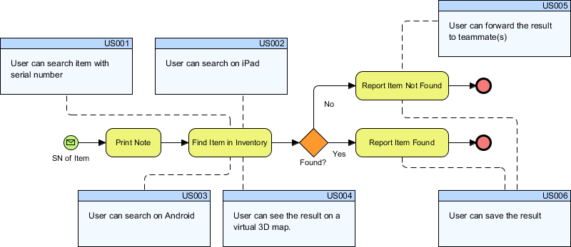
The diagram presented above represents a classic BPMN sequence flow integrated with user requirements. It visualizes a workflow where a user attempts to locate an item within an inventory system. The architecture relies on two distinct layers of information:
- The Process Layer (BPMN): This consists of the standard flow elements, such as tasks (rounded rectangles), gateways (diamonds), and events (circles). This layer dictates the logical order of operations.
- The Requirements Layer (User Stories): These are the blue boxes labeled
US001throughUS006. These represent the functional requirements from the perspective of the end-user.
The key architectural feature here is the use of connectors to link these two layers. By drawing a line from a User Story to a specific BPMN element, you establish a bidirectional link. This allows developers to trace a requirement back to its process step and vice versa.
Step-by-Step Modeling Guide
To replicate this advanced modeling technique in Visual Paradigm, follow the logical steps below to create a layered, traceable BPMN model.
Step 1: Define the Process Flow
Begin by modeling the standard business process. For this example, we model a search process:
- Start Event: Represented by the green circle icon, triggered by the input “SN of Item” (Serial Number).
- Tasks: Define the actions “Print Note” and “Find Item in Inventory”.
- Gateway: Insert an Exclusive Gateway (the orange diamond) labeled “Found?” to introduce decision logic.
- Outcomes: Create paths for “Yes” (Report Item Found) and “No” (Report Item Not Found), terminating at End Events.
Step 2: Create the User Story Layer
In Visual Paradigm, you can create a specific diagram type or layer for requirements. To keep the diagram clean, we will place User Stories on a separate visual layer.
- Create a text box or a specific requirement element for each user story.
- Assign a unique ID to each, such as
US001,US002, etc. - Define the content using standard User Story syntax: “As a [role], I want [feature] so that [benefit].”
Step 3: Mapping Requirements to Process Elements
This is the core of the architecture. You must map the User Stories to the specific BPMN elements they support. This is achieved using a Connector (often a dashed line in this style).
Here is the logical breakdown of the mappings shown in the diagram:
- US001 (Search by Serial Number): Linked to the “Print Note” task, indicating the system must allow input of the serial number to print a note.
- US002 (Search on iPad) & US003 (Search on Android): Linked to the “Find Item in Inventory” task. This implies that the search functionality is accessible via both iPad and Android devices.
- US004 (Virtual 3D Map): Linked to the “Find Item in Inventory” task. This adds a visualization constraint to the search result.
- US005 (Forward Result): Linked to the “Report Item Not Found” task, suggesting a communication feature is available in this state.
- US006 (Save Result): Linked to the “Report Item Found” task, indicating a persistence requirement for successful searches.
Benefits of the BPMN + User Story Approach
Integrating these two methodologies offers several strategic advantages for requirements management:
1. Clarity and Visualization
BPMN diagrams provide a clear, structured representation of business processes. By mapping user stories to BPMN diagrams, you ensure that every aspect of the business process is covered in the form of user stories. This clarity helps in capturing all requirements effectively.
2. Traceability
Mapping user stories to specific BPMN elements creates a traceable link between high-level business processes and detailed system requirements. This traceability ensures that every user story is directly related to a specific process step, making it easier to track progress and changes.
3. Visibility Control
Creating a separate layer for user stories allows you to control their visibility in BPMN diagrams. This is particularly useful during discussions with stakeholders who may not want to see user stories but are more interested in understanding the overall process flow. You can toggle the visibility of the US... boxes to present a clean process map to executives.
4. Change Management
When changes are required in the system, having user stories mapped to BPMN processes makes it easier to assess the impact of those changes. You can quickly identify which parts of the process need modification and update the corresponding user stories accordingly.
Tooling: Visual Paradigm
Visual Paradigm is a robust modeling tool that supports this specific workflow out of the box. It provides the flexibility to mix standard BPMN 2.0 notation with custom requirement elements.
Key Features in Visual Paradigm
- BPMN 2.0 Standard Compliance: Ensures your process diagrams (Start, Task, Gateway, End) adhere to international standards.
- Requirement Management: The tool supports creating and linking requirements, allowing for a seamless transition from design to code.
- Connectivity: The diagramming canvas supports standard connectors, which can be styled (e.g., dashed lines) to distinguish requirement links from process flow.
- Documentation Generation: Once mapped, you can generate documentation that automatically lists the User Stories associated with each process step.
By utilizing Visual Paradigm, you gain a structured approach to requirements management that offers clarity, visualization, traceability, and improved communication between stakeholders. This integration facilitates a smoother transition from business processes to software development, leading to more successful project outcomes.